Investigating a new FPGA board
As I explained in the previous post, I have acquired a Microphase Z7-Lite board, in order to check if it could be used as a possible platform for zeST.
As it is currently taking most of my time on zeST development, I am writing this post so you can understand what I am doing at the moment.
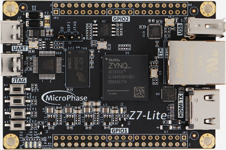
Meet the Microphase Z7-Lite board
It is the cheapest I could find with the required elements I need: A Xilinx Zynq-7000 FPGA SoC, a SD card slot, sufficient memory, a HDMI port and some USB connectivity. Other peripherals like ethernet could be useful for future extensions.

A different board
Although it is using a FPGA from the same family as my previous board, the general design is very different. One of the least important differences is that it has only one 16-bit DDR memory chip, allowing a 16-bit only memory data bus. I am confident this is not a problem, since the major drawback with DDR is its latency, not the data throughput, and even with a reduced data bus width I am pretty sure it will be usable.
The Z-Turn board on which I first designed zeST is more oriented toward designs centered around the Zynq’s “PS” (processing system, the part of the chip with the Arm CPU and embedded hardware controllers), making the hardware components programmed on the “PL” (programmable logic, the FPGA part of the chip) as peripherals of the CPU. This new board makes the PL components much more independent, as it is possible to make full designs without using the PS at all.
The major particularities of this board are:
- Ethernet is not connected to one of the dedicated Zynq pins that make it directly accessible from the PS, but instead on some PL I/O pins. So the hardware designer can program their own hardware controller and “plug” it directly to the ethernet PHY, the physical port controller. I am not really interested with that for the zeST project, and whenever I need ethernet I will probably figure out a way to use one of the embedded PS ethernet controllers anyway.
- The pins of the HDMI port are directly accessible to the PL. On the Z-Turn board, the HDMI video output is managed by a HDMI transmitter chip on the board. Here, the FPGA must directly generate the HDMI signal.
The HDMI transmission problem
With the Z7-Lite board comes a large amount of documentation (in Chinese, but thanks to automatic translation it is very usable to me anyway).
There are two principal examples provided about how to use the HDMI port. One is a very simple design that outputs a 1920x1080p image, and the other makes use of a Xilinx IP core with full HDMI capability.
The first design is a good example for a basic design with only 1080p images and no sound output. It mostly generates a DVI signal (HDMI is retro-compatible with DVI), with just video data and sync controls. HDMI is a much richer protocol with extra data carried along with the video signal: it allows extra information about aspect ratio, colour rendering, among many others. And moreover, HDMI also allows to output sound, which was not supported by DVI.
Using the Xilinx IP core could be a solution, as it is a full-featured HDMI transmitter that can be programmed on the FPGA, completely removing the need for an external chip. The problem is that the designer must pay a license to be able to use it, which is not exactly compatible with the FOSS idea I am having around zeST.
So what we need is an open-source design sufficient for our video output needs, that also enables sound output. I have actually stumbled upon another project like that (see here), but it looks more like a video controller with fixed legacy resolutions than just a HDMI transmitter that takes a video signal from a video controller and generates the cleanest possible HDMI output signal for the monitor that is connected to it. Besides, as I explan in the next paragraph, I need to output video that is produced by the ST shifter from the zeST design.
On the way to a custom HDMI transmitter
When using the Sil9022A HDMI transmitter chip on the Z-Turn board, I could provide video signals coming from the shifter, possibly using the simple scan doubler hardware that I made to enable more VGA-compatible signals. I suppose the Sil9022A did a fair amount of signal conversion to generate a HDMI signal that is adapted to the connected monitor, because so far on the new board, I could not output anything different from a 1080p image, even using fully standard and HDMI mandatory low resolution modes like 576p.
There’s something missing in what I am doing, and that could be I need to provide the exact required timings of the monitor. Each monitor has its own requirements for video modes, especially the duration of the horizontal and vertical sync activations, the delay between syncs and pixel output etc.
The HDMI controller has a way to get the descriptions of the possible video modes directly from the monitor, and my current work is to use that data to generate the cleanest HDMI signal as possible.
I believe once I have managed that, sound output will not be too complicated to implement, and I will be able to implement the rest of zeST and see if everything works.
That’s all folks!
Thank you for reading this post! If you have comments and thoughts about this post, you can comment on the corresponding tweet.